![[*]](foot_motif.gif) .
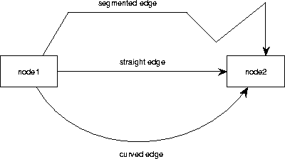
For this, turn on the Curve toggle in the tiled menu. The Bezier
curve requires exactly two intermediate points,
which makes four edge points in total. These intermediate points
are added in the same way as creating normal multiple line segments as
described for segmented edges. When the four points are
determined, a smooth curve is drawn between the end points and
the two intermediate points act as controlling points.
.
For this, turn on the Curve toggle in the tiled menu. The Bezier
curve requires exactly two intermediate points,
which makes four edge points in total. These intermediate points
are added in the same way as creating normal multiple line segments as
described for segmented edges. When the four points are
determined, a smooth curve is drawn between the end points and
the two intermediate points act as controlling points.
After creating the edge, the edge is selected which is visible by a selection handle on each line point. You can adjust the line points by moving the handles; see section 3.6.
When an edge is created and it is the only straight edge
connecting this particular couple of nodes, it will go (virtually) through
the center points of the nodes. When there are multiple straight edges
connecting the same pair of nodes, they will be equally distributed
by default over the opposing sides.
Segmented and curved edges are not equally distributed when they
connect the same pair of nodes. TCM tries to intersect the first
and last segment of a segmented line orthogonally with the sides of the
connected nodes. If this is geometrically impossible, the segment will
be directed to the center of the node like with straight edges .
Tip: When you want to enforce that a straight edge is always orthogonal to a node, then you can draw a segmented line of three points that looks like a straight line. You enforce then that the line is always connected orthogonally with both of the nodes (providing that this is geometrically possible). This gives often a more pleasant optical result when you want to connect two nodes that differ a lot in size.
It is possible to move the end points of an edge as well, in the same way as you move the intermediate points. When you drag the handle of an end point to another position then the new end point will be the position at the border of the node shape that is the closest to where you released the handle. However, when you drag the handle of an end point into a different node shape then the edge will be redirected to that node.