 16. Windows and Viewports.
  16. Windows and Viewports.
 In Ian Angell's Calcomp system, the world co-ordinate units are
This is not the only possible dimension for our graphics area.
    0.0 --> 22.0 in the x direction and

    0.0 --> 16.75 in the y direction.
It would be nice if the (x,y) upper and lower bounds were
flexible so that a different size could be catered for.
For example:
 if a house specified (x,y) measurements that ranged from -120 to

503 feet in the x direction and -50 to 430 feet in the y

direction.


or as in the assignment, xmin and xmax, ymin and ymax are not in

the required Calcomp range.

WINDOWS - the mapping of dimensions onto the image area - have

three normal uses:


      (1) drawing area = window area      normal size image

      (2) drawing area < window area      reduced size image

      (3) drawing area > window area      magnified and clipped image.

A window always maps the (x,y) co-ordinates onto the entire display area. Therefore if the (x,y) pairs do not use the entire window area then Figure 16.1(b) results. If the (x,y) pairs would draw lines outside the window area then those lines must be clipped.
It is now possible to zoom in on areas of our image by
changing the window that we see. For example if we set our new
window co-ordinates xmin and ymin to point to a certain area of
the image, set the x and y range accordingly, and then drew the
picture, we would get a magnified (reduced) image that is
clipped.
Windows and World Co-ordinates: This is just expressing the co-ordinates of the screen or plotting surface in some abstract units (which give better resolution than you would normally be able to get from any known graphics device.) We have chosen to use "screen inches" as our abstract units and by choosing our units to be real numbers we have nearly infinite resolution.
Our individual drivers take the world co-ordinates and turn
them into integer co-ordinates for the particular device. This
also enables us to display images with more resolution than the
device is capable of normally displaying, i.e. displaying an
image 4096x4096 pixels on a T4010 screen would mean that 4 pixels
are mapped into 1 in horizontal direction and 5 to 1 in vertical
direction.

Xmap = 4096/1024; Ymap = 4096/780

Often it is convenient to only look at a small part of an image. How do we transform it to shrink it (or enlarge it)? Use windows! We provide a window on the whole image through which we only see a little bit or the whole image made smaller.
It may be that the display has to show a number of images
produced with different windows (See Figure 16.3). Remember that
any window maps onto the entire viewing surface of our display.
and hence we would need to scale and translate each separate
image onto the viewing surface. Rather than do this we use the
concept of a viewport or viewing area. Instead of the window
mapping onto the entire screen, it is mapped into a smaller
viewing area called a viewport.

For example the normal 22.0 x 16.75 window could be scaled and

translated to (say) xlow,ylow = (10,4) and xhi,yhi = (12,12).

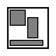
This is the very skinny viewport shown in Figure 16.2.


Fig. 16.2 : Viewport example

       call       setwindow(xlo,xhi,ylo,yhi)

        { now set viewport using ratio of boundary of

          viewport to boundary of window.              }

       call       setviewport(a,b,c,d)

       { generate image..... }


       call       setviewport(e,f,g,h)

       { generate image..... }


       call       setviewport(i,j,k,l)

       { generate image..... }

Note that we can have overlapping viewports and that our window may contain only part of the image and hence our viewport contains the image clipped. Therefore we have to apply our clipping algorithm to the viewport to remove (or not draw) unwanted vectors.

Fig. 16.3 : Multiple Viewports

 Since not all transformed lines are displayed, it is better to clip

first then transform.


Therefore clip lines not within WINDOW and then transform these to

the VIEWPORT.

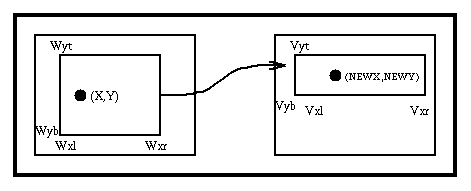
Finally lets look at the transformation of real World Co- ordinates into device pixel co-ordinates.
NEWX = (Vxr-Vxl)*(X-Wxl) / (Wxr-Wxl) +Vxl

Fig. 16.5 : World transformation
What is our transformation that takes world co-ordinates
into screen T4010 co-ordinates?

        X displayed = (1023 -0) * (X-0.0) / (22.0-0.0) + 0


                      = 1023/22.0*X


        Y displayed = (780 -0) * (Y -0.0) / (16.75 - 0.0) + 0


                      = 780/16.75 * Y

Many micros such as the Lisa, MacIntosh, Apricot, etc have roll-down areas on the screen that can be used to hold temporary text or images. After the area has been used it rolls up off the screen (or disappears) and the text/image that was underneath it is reconstructed.
The micro manufacturers call these areas windows although they are barely viewports. Some of these "windows" can be moved around the screen, some are fixed and the information in them is not scaled - it is just text or normal size images. Others are true viewports in that they can be moved and the information within the "window" is scaled to the viewport dimensions. Since multiple overlapping "windows" are usually allowed the software to handle these can become complex. The updating of the screen after a "window" has been rolled up or removed can also take a long time.


