 7.5. Concerning Form Factor
  7.5. Concerning Form Factor
 After a given environment is broken down into a set of polygons, energy exchange between all pairs of elements are evaluated. This evaluation is called Form Factor calculation.
There are a number of problems associated with form factor in the radiosity method. These are:
The definition of form factor is : an expression of the radiative exchange between two patches or the fraction of energy leaving one patch that arrive at other [Goral,84][Watt,92]. Form factor only depends upon geometry of patches such as size, orientation and distances. Thus, once the form factors have been calculated for a given environment, they remain unchanged providing the geometry does not change. Patch reflectances and emissivities can be changed without requiring the recomputing of the form factor values [Hall,89].
Consider a form factor between two infinitesimal surfaces
with differential areas dAi and dAj.
As from above diagram, dw is the solid angle subtended by dAj as seen from dAi. Its value is:

Fig. 7.24 : Form Factor


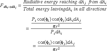

 Aj is
Aj is


In 1985, Cohen introduced a comprehensive method by using a hemicube which effectively calculates the form factor values and solves the problem of the intervening patches in a complex environment.
As we have seen, the patch_to_patch form factor is:


In his method, Cohen uses the Nusselt analogue to determine
visibility in complex environment. According to Nusselt's
analogue, for a finite area, the form factor of the patch is
equivalent to the fraction of the circle at the base of the
hemisphere. The circle is formed by taking the projection of the
patch onto the hemisphere surface and projecting it down onto the
base of the hemisphere. Nusselt's analogue also said that any
patch that has the same projection area on the hemisphere surface
has the same form factor value. The diagrams below shows the
Nusselt analogue clearly.
Cohen uses a hemicube instead of a hemisphere for the convenience of geometry specifications. An imaginary unit size hemicube is positioned at the center of the front face of each patch such that the base of the hemicube is perpendicular to the normal of the patch. The faces of the hemicube are then subdivided into small elements called pixels (NOT to be confused with the pixels on the screen).
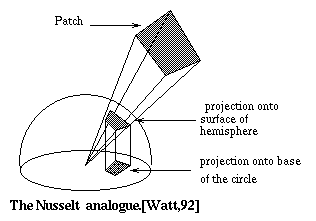
Fig. 7.25 : Nusselt analogue
Each pixel on the hemicube is considered as a small patch. By using Nusselt's analogue, each patch j in the environment is projected on the hemicube of patch i. Delta form factors are then precomputed for each pixel of the hemicube and stored in a look up table. Delta form factors are the form factors computed from the center of the base of the hemicube to a pixel on the hemicube. The form factor from a patch i to another patch j is the sum of the delta form factors covered when patch j is projected onto the hemicube surface of patch i.
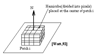
Fig. 7.26 : A different type of pixel
By using the hemicube method, the occluding or intervening patch problem is easily solved. As mentioned above, if any two patches have the same projected area on the hemicube surface, then they have equal form factor values. When patches are projected onto the hemicube, if one pixel contains the projection from two patches, then the distance between pixel and each patch is determined and we select the nearer patch. Thus, for each pixel on the hemicube , there is a patch label buffer which contains the patch number that is seen by that particular pixel. It is very similar to Z-buffer algorithm concept.
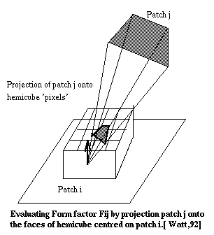
Fig. 7.27 : Form Factor Evaluation
Therefore, the form factor of patch i and j becomes:
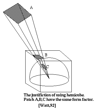
Fig. 7.28 : Hemicube Justification

The delta form factor Fq is given as:
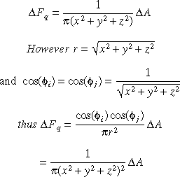
There is an algorithm for hemicube and delta form factor.
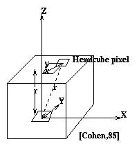
Fig. 7.29 : Hemicube pixels
The general idea of hemicube and hemisphere is the same, the difference is only the way they approach the intervening patch problem. There are some problems involved in these methods which are mainly due to the use of discrete uniform sampling through the pixels of the hemicube. The problems are as follows:
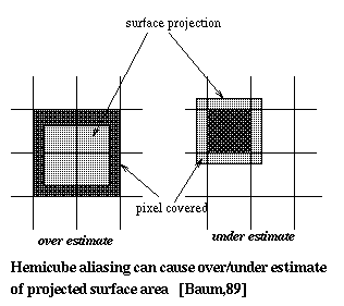
Fig. 7.30 : Hemicube Aliasing
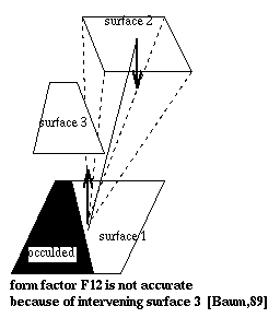
Fig. 7.31 : Occlusion
This method was introduced by Baum [Baum,89] in 1989. This is one step beyond the normal hemicube algorithm while retaining the major benefit of hemicube algorithm - computational efficiency. As mentioned above, the hemicube form factor method is inappropiate when patches are too close relative to their sizes and the environment involves light sources. In Baum's method, form factors are evaluated analytically and use a hemicube to determine the visibility only.
The form factor from patch i to patch j is given as (detail
explained in hemi cube section)

The inner integral, a differential area to finite area
form factor is then calculated as :
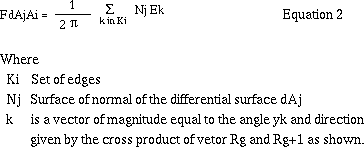
The above formula is later used to determine an element to patch form factor.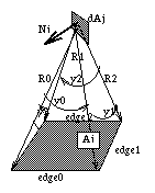
Fig. 7.32 : Baum's Method
The detailed description of Baum's method is as follows:
Like the hemicube method, each element in a patch is
projected onto the hemicube pixels. For each pixel onto which an
element projects, the form factor is calculated by using equation
1. This is weighted by the area of pixel projected onto the
element (divided by the total visible area). The outer integral ,
patch to patch form factor, is then evaluated by summing the
above element form factors. That is done by normal hemicube
algorithm.
Element to patch form factor, Fej, is weighted by the average of the samples. Because of the magnitude of Fej does not depend directly on the number of pixels projected on the hemicube, it solves the aliasing problem due to an element projecting onto a small number of hemicube pixels. To solve the intervening patches problem, Baum suggested that each shooting patch should be subdivided until the subdivision components are either fully visible or fully hidden from each element in the environment.
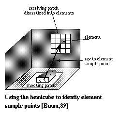
Fig. 7.33 : Sample points
To determine whether subdivision is need or not, the
following equation is carried out after finding all the element
to patch form factors for patch i.

If the sum is greater than unity by a significiant amount then visibility errors exist for more than one surface in the scene. In this case, the shooting patch needs to be subdivided ,and the procedure recursively applied to each subpatch.
Immel [Immel,86] presents the determination of radiance distribution using a global cube. In the hemicube method, each hemicube is constructed on every patch and visibility is determined by looking through the each pixel of the hemicube. The hemicube is also oriented so that the patch normal always coincides with the center of the hemicube's top face. Since the orientations of the cubes are determined by patch's local coordinate system, there is no directional relationship between the hemicubes. However, the traditional radiosity method assumes that the intensity is constant over all the directions , hence, the directional relationship is not that important.
When the intensities vary with the directions, it is
important to equate the incoming directions of receving patch
with the reciprocal outgoing directions from the sending patches.
In that event, instead of reorienting a hemicube, Immel suggested
that an imaginary full cube is constructed along the global axes
instead of reorienting a hemicube.
Each face of the global cube is stored as a vector of the visible patch indenticfication numbers. For example, the faces of the cube are oriented as diagram a and the the vector is ordered as diagram b, then the reciprocal global cube locations may be easily calculated. The benefit of this is if patch i sees patch j through the cell oriented in the X,Y,Z direction, then reciprocal cell from patch j is simply in the -X,-Y,-Z direction.
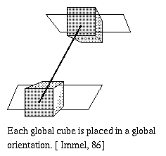
Fig. 7.34 : Global Cube
During the rendering process, after specifying an eye position and view direction , the intensities coming to the eye are determined from the global cube directional intensities. Those intensities are the intensities at the grid vertices in the scene which are seen from that direction. The grid vertices are obtained by bilinearly interpolating between the nearest vertex cube directional intensities. Pixel intensities are then bilinearly interpolated from the vertex intensities.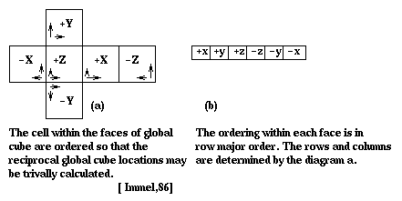
Fig. 7.35 : Immel's Method
Source to vertex form factor is presented by Wallace[Wallace,89] to use in progressive refinement radiosity solution. Previously, the hemicube method was used. Unfortunately, it is not appropiate for progressive refinement due to its aliasing problems. Hemicube aliasing occurs when there are an inadequate number of pixels on the hemicube and the number of hemicubes that are used for source patches. These problems are eliminated in this new method.
In previous methods, form factors are determined by viewing the scene from the source and finding out which surfaces are visible. These method neglected the fact that the renderer will be using the patch vertex intensities for the final shading. Vertex intensities are determined by interpolating the intensities of neighbouring pixels , hence, inaccuracy may be result. In this new method, form factors are evaluated from source to receiver vertices by shooting rays from each vertex to sample points on the source. In that way, it is guaranteed that projected rays coincide with the polygon vertices.
To evalute the source to vertex form factor, the source (which currently possess the greatest amount of energy) is subdivided into delta areas. The form factor from each delta area to vertex is then calculated. Occlusion is determined by shooting a single ray from receiving vertex to the center of the delta area on the source. During the progressive refinement, at each stage form factors are computed from every vertex to the current source.
Of course, the accuracy of form factor depends on the number of rays shot. Those rays can be increased by simply increasing the number of sample points on the source. Those points can be varied from vertex to vertex as necessary since form factors from source to vertex are computed independently of other vertices.
To get an accurate form factor, the delta area on the
source is recursively subdivided for each receiver vertex until
the form factor from vertex to delta area falls below a user
specified criterion. This method also eliminates aliasing by
jittering the location of the sample points on the source.
To evalute the source to vertex form factor, we will start with the form factor for differential area dAv3s to a differential dAs which was used in hemicube pixel contribution:
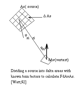
Fig. 7.36 : Progressive refinement


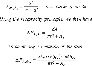

But we know that the energy leaving the source is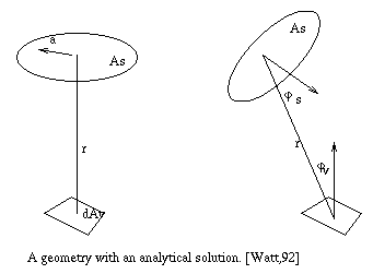
Fig. 7.37 : Analytic solution

BvAv = PvBsAsFsv


