

Next: C.2 Behavior View Notations
Up: C Mini-tutorial on Notation
Previous: C Mini-tutorial on Notation
Subsections
The TCM convention for ERDs is described in detail
in [18, chapters 7, 8].
As usual, a named rectangle represents a named entity type.
Binary relationships are presented by lines.
Cardinality constraints are represented by
annotations placed at the end points of these lines.
Figure C.1:
The placement of cardinality constraints.
 |
For example, in figure C.1, each business has an employment
relationship to more than zero persons and each person has 0 or 1
employment relationships to a business.
The end points of the line can also be annotated with the role that the
entity at that end of the line plays in the relationship.
Figure C.2 gives an example.
Figure C.2:
The placement of role names.
 |
Figure C.3:
The meaning of cardinality constraints.
 |
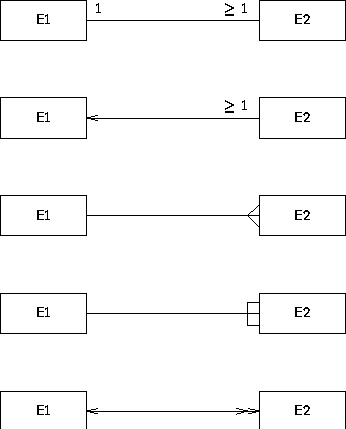
In general, a cardinality constraint is represented by a set of natural
numbers (see figure 4.4 for the syntax).
For example, if c is a set of natural numbers, the constraint
in figure C.3 is that each instance of E1 is related
to n instances of E2, where  c
c ![[*]](foot_motif.gif) .
If no constraint label is shown, the convention is that the constraint is
the entire set of natural numbers, i.e. it is no constraint.
For example, in figure C.3, each instance of E2 is
related
to any number instances of E1.
This includes the case that it is related to 0 instances of E1.
.
If no constraint label is shown, the convention is that the constraint is
the entire set of natural numbers, i.e. it is no constraint.
For example, in figure C.3, each instance of E2 is
related
to any number instances of E1.
This includes the case that it is related to 0 instances of E1.
Figure C.4:
The arrow representation of many-one constraints.
 |
There are various conventions for the placement of the cardinality
constraints, all of which are a source of confusion.
The choice made in TCM is motivated as follows.
We use the convention that a cardinality constraint of 1 can be abbreviated
by an arrowhead.
So the two diagrams in figure C.4 are equivalent as far as
their cardinality constraints are concerned.
They both mean that each person is related to exactly 1 business and that
each business is related to at least one person.
This means that the relationship is a mathematical function from persons to
businesses, which explains the arrow convention.
To facilitate a smooth transformation between these two representations,
the cardinality constraint labels must be placed where they now are.
Figure C.5:
The line representation of binary relationships is direction-independent.
 |
Note that the naming of the relationship usually must change when we switch
to the arrow notation.
In the line notation, there is no natural reading direction for the
relationship name.
For example, figure C.5 conveys the same information as
figure C.1.
In the arrow representation, by contrast, there is a natural reading
direction and we adapt the relationship name accordingly.
Often, the role name of the entity type at the arrowhead becomes the
relationship name.
Figure C.6:
Different conventions for representing the same constraints.
TCM supports the conventions used in the upper two diagrams.
 |
Figure C.7:
Different conventions for representing the same constraints.
TCM supports the conventions used in the upper two diagrams.
 |
There are many other conventions to represent binary relationships.
Figure C.6 shows different ways of representing the following
constraints:
-
Each existing E1 is related to at least one existing
E2 and
-
Each existing E2 is related to exactly one existing
E1.
Figure C.7 shows different ways of representing the following
constraints:
-
Each existing E1 is related to at any number (including 0)
existing E2 and
-
Each existing E2 is related to exactly one existing
E1.
Figure C.8:
The diamond representation for relationships.
 |
A relationship is a Cartesian product of two or more entity
types, called its components.![[*]](foot_motif.gif) Relationships of arity higher than 2 are represented by a
diamond, connected by arrows to the boxes that represent its components.
These arrows represent the projection functions of a Cartesian product on
its components.
Figure C.8 contains exactly the same information as
figure C.1.
Note the placement of the cardinality constraints, which is at the root of
the arrow.
This agrees with the placement convention of constraints on relationship
lines.
In fact, one can view the arrows in figure C.8 as binary
relationships between EMPLOYMENT and its two components.
The meaning is that each business is related to at least one employment
instance (and hence to exactly one person),
and that each person is related to exactly one employment instance (and
hence to exactly one business).
This agrees with the meaning of figure C.1.
Relationships of arity higher than 2 are represented by a
diamond, connected by arrows to the boxes that represent its components.
These arrows represent the projection functions of a Cartesian product on
its components.
Figure C.8 contains exactly the same information as
figure C.1.
Note the placement of the cardinality constraints, which is at the root of
the arrow.
This agrees with the placement convention of constraints on relationship
lines.
In fact, one can view the arrows in figure C.8 as binary
relationships between EMPLOYMENT and its two components.
The meaning is that each business is related to at least one employment
instance (and hence to exactly one person),
and that each person is related to exactly one employment instance (and
hence to exactly one business).
This agrees with the meaning of figure C.1.
Value types (often called ``data types'') are represented by ovals.
Entity attributes are represented by arrows from an entity type to an
oval
and relationship attributes are represented by arrows from a relationship
diamond to an oval.
This means that the TCM convention does not distinguish between
``ordinary'' relationships, which do not have attributes, and ``associative
entity types'', which are relationships that can have attributes.
Figure C.9:
The representation of is-a relationships.
 |
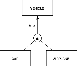
An is-a relationship is a binary relationship that is an inclusion
function.
For example, figure C.9 shows that each CAR instance
is also a VEHICLE instance.
Extensionally, the set of all possible cars is a subset of the set of all
possible vehicles.
Intensionally, the set of properties shared by all cars includes the set of
properties shared by all vehicles.
CAR is called a specialization of
VEHICLE and VEHICLE is called a generalization of
CAR.
If there is more than one specialization of an entity type, then these must
be grouped into specialization groups.
This is represented by connecting the rectangles representing the
specializations
to a small circle
called the taxonomy junction and connecting this with an
is-a arrow to the rectangle representing the generalization.
The taxonomy junction must be annotated as follows:
-
A ``d'' means that the
specializations are mutually disjoint.
-
An ``e'' means that the specializations
jointly exhaust the generalization.
-
A ``de'' means the conjunction of ``d'' and
``e'', i.e. the specializations partition the generalization.
A generalization can be specialized by any number of specialization groups.
For example, figure 4.5 means the following:
- Cars are vehicles and trucks are vehicles.
-
The union of the set of all cars and all trucks equals the set of all
vehicles.
So vehicles are trucks or cars (or both).
- Diesel vehicles are vehicles and gas vehicles are vehicles.
-
There is no vehicle both a diesel and a gas vehicle.
- There may be vehicles that are neither diesel nor gas vehicles.
The CRD notation of TCM follows the convention that a class is represented
by a rectangle subdivided into three areas, that contain, from top to
bottom, the class name, the attributes, and the events that can occur in
the life of the class instances.
TCM can hide one or both of the event and attribute areas from view.
Figure C.10:
The CRD representation of relationships.
 |
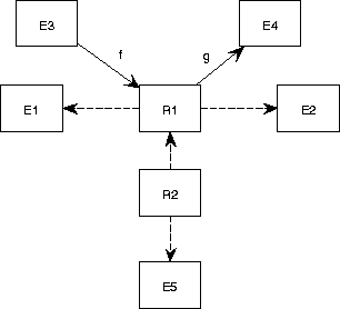
Relationships are represented by rectangles just as classes are.
They are connected to their components by means of dashed arrows.
The meaning is exactly the same as in the ERD case.
Figure C.10 has exactly the same information content as
figures C.1, C.5 and C.8.
The line representation (figure C.1) is also allowed in the
CRD convention.
The advantage of the CRD convention over the diamond representation
is that a rectangle allows easier
placement of text inside the area.
In addition, the CRD convention used in TCM allows representation of such
complex structures as represented in figure C.11, which cannot
be represented in the ERD convention.
Figure C.11:
The CRD convention can represent complex mathematical structures.
 |
Figure C.11 represents the following structures.
(To reduce clutter in the notation, we ignore the fact that
relationships are actually labeled Cartesian products.)
- R1 = E1
 E2
E2
- f : E3
 R1
R1
- g : R1
 E4
E4
- R2 = R1
 E5
E5
Figure C.12:
Static specialization.
 |
The CRD convention for representing is-a relationships extends the ERD
convention with constructs to represent static and dynamic specialization.
A static specialization group is represented by a small closed circle,
called a taxonomy junction,
and
a dynamic specialization group is represented by a dashed circle, called a
mode junction (see figure 4.7).
In figure C.12, an instance of CAR will never
become an instance of AIRPLANE and vice versa.
An instance is a member of a specialization for life.
By contrast, in figure 4.11, an instance of MARRIED PERSON
may move to another of the subclasses of PERSON.
Here, an instance is an instance of a specialization only for part of its
life.
We call these specialization mode classes.
For example, MARRIED PERSON is a mode class of
PERSON, because a married person is a mode of a person.
Details of static and dynamic specialization are given
elsewhere [19,20].


Next: C.2 Behavior View Notations
Up: C Mini-tutorial on Notation
Previous: C Mini-tutorial on Notation
Frank Dehne,Faculty of Mathematics and Computer Science, Vrije Universiteit Amsterdam
11/17/1997
![[*]](foot_motif.gif) .
If no constraint label is shown, the convention is that the constraint is
the entire set of natural numbers, i.e. it is no constraint.
For example, in figure C.3, each instance of E2 is
related
to any number instances of E1.
This includes the case that it is related to 0 instances of E1.
.
If no constraint label is shown, the convention is that the constraint is
the entire set of natural numbers, i.e. it is no constraint.
For example, in figure C.3, each instance of E2 is
related
to any number instances of E1.
This includes the case that it is related to 0 instances of E1.


![[*]](foot_motif.gif) Relationships of arity higher than 2 are represented by a
diamond, connected by arrows to the boxes that represent its components.
These arrows represent the projection functions of a Cartesian product on
its components.
Figure C.8 contains exactly the same information as
figure C.1.
Note the placement of the cardinality constraints, which is at the root of
the arrow.
This agrees with the placement convention of constraints on relationship
lines.
In fact, one can view the arrows in figure C.8 as binary
relationships between EMPLOYMENT and its two components.
The meaning is that each business is related to at least one employment
instance (and hence to exactly one person),
and that each person is related to exactly one employment instance (and
hence to exactly one business).
This agrees with the meaning of figure C.1.
Relationships of arity higher than 2 are represented by a
diamond, connected by arrows to the boxes that represent its components.
These arrows represent the projection functions of a Cartesian product on
its components.
Figure C.8 contains exactly the same information as
figure C.1.
Note the placement of the cardinality constraints, which is at the root of
the arrow.
This agrees with the placement convention of constraints on relationship
lines.
In fact, one can view the arrows in figure C.8 as binary
relationships between EMPLOYMENT and its two components.
The meaning is that each business is related to at least one employment
instance (and hence to exactly one person),
and that each person is related to exactly one employment instance (and
hence to exactly one business).
This agrees with the meaning of figure C.1.