


Next: C.3 Function View Notations
Up: C Mini-tutorial on Notation
Previous: C.1 Data View Notations
Subsections
Figure C.13:
The Mealy representation of state
transition diagrams.
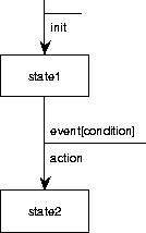 |
TCM supports the Mealy notation for finite state transition diagrams
(figure C.13).
States are named, and are represented by rectangles.
State transitions are represented by arrows and are labeled by
event[condition]/action pairs.
The event is the trigger
of the transition and can be viewed as the occurrence of an input.
The condition is a guard.
The precise meaning of the guard depends upon the method in which the
notation is used.
A minimalistic interpretation is that if the guard is false, an
occurrence of the event will not trigger the transition.
A more closed interpretation is that additionally, if the guard is
true, an occurrence of the event will trigger the transition.
It also depends upon the method what kinds of conditions can occur in
the guard.
The current version of TCM does not support any method in particular
and therefore imposes no constraints on what one can put in a guard.
The action part of the transition label is the output action generated
by the transition.
Each Mealy STD must have an initial state, pointed at by an arrow that
leaves from no node, and that can be labeled by an initialization
action.
TCM also has decision points
which are intermediary states
that the machine may have between system transactions. Decision
points are represented by a hexagon.
Mealy machines are used in Yourdon-style structured analysis, where
they are used to specify control processes [23].
The interface of the control process must equal the interface of the
Mealy machine.
See section C.3.2 for control processes.
Figure C.14:
A process structure diagram.
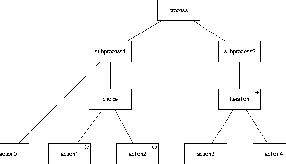 |
Process structure diagrams are used in JSD to represent behavior.
A PSD is a tree in which the nodes are
labeled [9], [18, chapters 11, 12].
The leaves of the tree represent atomic actions and the root
represents the entire process.
Sequence is represented by a left-to-right ordering of the children of
a node.
Iteration is represented by an asterisk label and choice by a small
circle in the nodes that represent the options.
Figure C.14 gives an example.
PSDs are equivalent to regular expressions.
Figure C.15:
A Mealy diagram roughly equivalent
to figure C.14.
 |
A Mealy machine roughly equivalent to this is shown in
figure C.15.
The names of the nodes in a PSD can be reused as state names in a
Mealy STD.
However, the Mealy convention forces us to categorize an action as an
input or output action, whereas in PSDs this is not the case.
In figure C.15
we arbitrarily categorized all PSD actions as output actions.
In JSD, PSDs are used to represent processes in reality and to
represent processes in the machine.
If used to represent processes in reality, common actions between PSDs
represent synchronous communication between these processes.
If used to represent processes in the software, communication between
processes is represented by means of system network diagrams, described
in section C.3.3 below.
Figure C.16:
A recursive process graph.
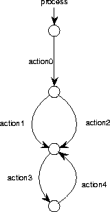 |
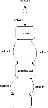
Figure C.17:
A recursive process graph with labeled nodes.
 |
A recursive process graph is a rooted directed graph in which the
nodes represent states and the edges represent atomic actions or other
processes.
Figure C.16 shows an RPG equivalent to the PSD of
figure C.14.
Nodes in RPGs can be labeled, just as in Mealy STDs.
Figure C.17 shows an RPG with labeled nodes.
An RPG has an initial node, which is pointed at by a small arrow and
which can be labeled by the name of the process.
Figure C.18:
A recursive process graph with a call to another process.
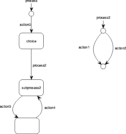 |
An edge in an RPG can be labeled with the name of an action or of a
process.
If it is labeled with a process name, the transition is equivalent to
performing this process.
Figure C.18 illustrates this.
The RPG in figure C.18 is equivalent to that of
figure C.17.
Figure C.19:
A recursive process graph with a recursive call.
 |
The call to another process can be recursive, as illustrated in
figure C.19.
This describes the process with possible traces  for
for  .
.
Recursive process graphs are defined formally by Spruit and
Wieringa [15], based upon the idea of recursive transition
networks [21].


Next: C.3 Function View Notations
Up: C Mini-tutorial on Notation
Previous: C.1 Data View Notations
Frank Dehne,Faculty of Mathematics and Computer Science, Vrije Universiteit Amsterdam
11/17/1997

