The TCM convention for DFDs is quite middle-of-the-road and follows mostly the DeMarco style [5], [18, chapters 9, 10]. A DFD is a directed graph with three kinds of nodes:
In figure 6.3, there are three processes, Confirm Registration, Check Request and Register students. When the external entity STUDENT sends a message test_request, which is a request to participate in a test, then the process Check Request retrieves the identifier of the test from the data store TESTS and the student identifier from the STUDENTS data store (the data stores are most likely implemented as files or in a database). If the test and student exist, and the student is allowed to participate in the test, then process Register students stores this fact in the TEST_REGISTRATIONS data store and Confirm Registration confirms this to the external entity. To make the DFD in figure 6.3 more precise, this model must be supplemented with precise process specifications, and a specification of the structure of the data stores and data flows.
DFDs can be hierarchical. This means that a process can be specified by means of another DFD, which has the same external interface as the process being specified. Such a process is called a compound process. A process specified in another way (e.g. by means of a piece of text) is called primitive. This can be indicated by the letter P in the node that represents the process.
Compound processes give rise to a tree of DFDs. Processes in this tree are labeled by means of a Dewey numbering system that indicates the location of the process in the tree. For example, process 1.2 is the process with label 2 in the DFD that specifies the compound process with label 1. The current version of TCM does not support hierarchical DFD editing. The next version is planned to provide this support.
DFDs can be combined with ERDs. The ERD should then represent the structure of the data in the data stores. The next version of TCM will provide this support.
DEFDs extend DFDs with a new kind of node, the control process, and
new kinds of edges: event flows and continuous flows.
A control process is represented by a dashed circle and represents an
aspect of behavior.
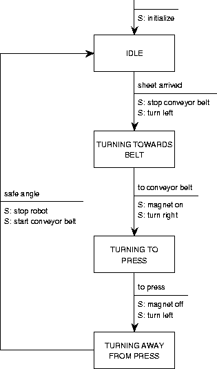
It must be specified by means of an STD that has the same interface as
the control process.
This means that the event flows entering the control process must
occur as events in the Mealy STD, and vice versa, and that the event
flows leaving the
control process must occur as actions in the STD, and vice versa.
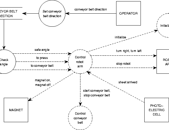
Figure C.20 contains a DEFD of which the control process is
specified in figure C.21.
 |
Event flows are represented by dashed arrows. An event flow can carry a signal without any data contents. The precise meaning depends upon the method that uses this technique. See for example the YSM manual [23].
A discrete flow carries a value that changes in discrete steps, a continuous flow carries a value that changes in a continuous way. Discrete flows are represented by arrows with a single arrowhead, continuous flows are represented by arrows with a double arrowhead. Again, the precise meaning depends upon the method used.
SNDs are used by JSD [9] to represent communication between processes. SNDs are directed graphs with two kinds of nodes, that represent processes and communications. A process node must be specified by a PSD, just as a control process in an DEFD must be specified by an STD. There are three kinds of communication nodes:
 |